

What role does membrane separation play in the tertiary vapor recovery at gas stations? Detailed explanation of the condensation and membrane combination process
Release time: 2026-10-06
View count:
The third-stage oil and gas recovery at gas stations treats the oil and gas discharged from the tank breather valve: the volume is small but persistent, and the concentration fluctuates with the pace of oil receiving and dispensing. Direct discharge not only results in oil loss but also poses safety and environmental protection pressures. In this end-of-pipe treatment line, the condensation unit is responsible for collecting most of the hydrocarbons, while the membrane separation unit acts as a gatekeeper - it concentrates and recycles the low-boiling-point components that cannot be fully collected by condensation, ensuring that the air on the emission side is sufficiently clean. The combined recovery rate of the two stages can stably achieve over 99%, and the emission concentration is controlled below 10 grams per cubic meter. This article clarifies the role of membrane separation in this process and the key points of configuration for the combined process.
How to separate oil and gas from air
The core of membrane separation lies in a non-porous and dense composite membrane: oil vapor molecules are first adsorbed and dissolved on the upstream surface of the membrane, then diffused through the membrane body driven by the pressure difference between the two sides of the membrane, and finally desorbed on the downstream side - this is the dissolution-diffusion mechanism. The rubber-like separation layer on the membrane surface has extremely high solubility for organic molecules, and the permeation rate of oil vapor through the membrane is several times to tens of times that of air, so oil vapor passes through preferentially while air is selectively retained. Since the membrane has no pores, there is no problem of pore blockage, the separation performance is stable, and there is no electrostatic accumulation during component operation, which provides a natural safety advantage for flammable and explosive oil and gas conditions.
How to coordinate condensation and film coating
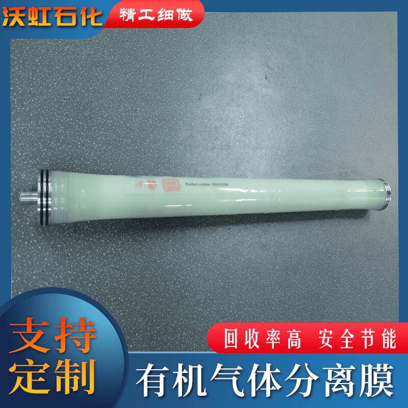
The entire process forms a closed-loop cycle: the tank breathing oil gas is pressurized by the compressor and enters the condensation unit, where the temperature is controlled at around zero to minus ten degrees Celsius. Heavy hydrocarbons above C5 are largely liquefied into liquid gasoline and returned to the storage tank; the uncondensed tail gas, which still contains low-boiling components such as butane, enters the membrane separation unit. Driven by the pressure difference across the membrane—pressure increase on the feed side and vacuum on the permeate side—oil gas molecules preferentially permeate through the membrane to form enriched gas, which is sent back to the compressor inlet for recycling treatment; the retained air hydrocarbon concentration has been reduced to a very low level, meeting emission standards. Condensation lays the foundation for the membrane, and the membrane complements the shortcomings of condensation, with the two stages working together without interference.
Why can the recovery rate exceed 99%
The key to recovery efficiency lies in each stage performing its own task: heavy hydrocarbons above C5 in gasoline components account for the majority of the total oil and gas, and most of them can be recovered at a condensation temperature around zero degrees Celsius; the remaining low-boiling components have a low concentration, and it is uneconomical to condense them separately. Membrane units are precisely adept at enriching organics in the low-concentration range. The enriched gas extracted from the permeate side is not discharged, but returned to the inlet for another cycle, where residual organics are repeatedly captured, resulting in an overall recovery rate of 99%. The concentration on the emission side is then stabilized to below 10 grams per cubic meter, leaving sufficient margin for meeting stricter emission requirements.
Configuration key points reference
| link | characteristic | Configuration considerations |
|---|---|---|
| Membrane separation layer | Rubber-like material, solubility-dominated | Select separation layer material according to the medium |
| Driving force | Partial pressure difference across the membrane | Raw material side pressurization and permeate side vacuum |
| Low boiling point component | Condensation is not fully collected | After membrane enrichment, return to the inlet for circulation |
| Emission side | Trapped air | Discharge after concentration reaches the standard |
| static electricity | No static accumulation on components | Open processing is safer |
| Membrane lifespan | Related to operating conditions | Pre-treatment plus pressure stabilization operation extension |
How to implement operation management
- Proper pre-treatment before membrane: filter and dehumidify to protect the separation layer;
- Record the trends of pressure difference and vacuum degree daily, and check the pre-treatment for abnormalities first;
- The vacuum pump is maintained according to the regulations, and the oil level and temperature rise are included in the spot inspection;
- The emission outlets are inspected according to frequency, and the data is recorded in the ledger to observe trends;
- Include explosion-proof zoning and electrostatic grounding inspection in the monthly checklist;
- The recycling volume and sales volume are reconciled on a monthly basis, and any anomalies are first investigated at the collection end.
Frequently Asked Questions
Will the membrane get clogged?
The membrane is a non-porous and dense structure, eliminating the issue of pore blockage. Most performance fluctuations arise from surface contamination of the separation layer. Proper filtration and dehumidification before membrane feeding ensures long-term stability. In case of abnormal pressure drop trends, first inspect the pretreatment section.
Is it possible to use only a membrane without condensation?
Yes, but it is more economical to collect the larger portion of condensate first when dealing with high concentration and large flow rate. The combined process integrates the strengths of both stages, achieving the best balance between investment and operating costs. It is also the mainstream configuration for tertiary recovery in gas stations.
Why should the enriched gas be returned to the compressor inlet?
The rich oil gas extracted from the permeate side has a high concentration but a small total volume. Returning it to the inlet for recycling not only prevents it from being discharged but also enhances the overall recovery rate. After forming a closed loop, only qualified air remains on the discharge side, making it cost-effective both on paper and from an environmental perspective.
This article is compiled by Luoyang Wohong Petrochemical Equipment Co., Ltd., which provides design, manufacturing, and operation and maintenance services for condensation recovery, membrane separation recovery, and complete solvent recovery equipment to chemical and pharmaceutical enterprises. If you need process evaluation or scheme configuration, please feel free to contact us for discussion.